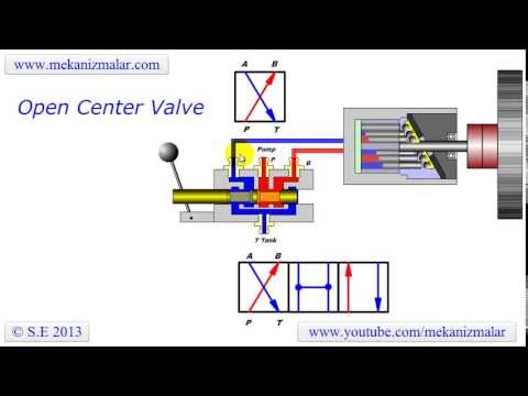
Open Center Valve Schematic
Basic valve design. (a) photograph of the single-valve device. (b, c Control valves valve work actuator stem move used 4 way 2 position valve schematic
Valve | Engineering | Fandom powered by Wikia
Open center valve schematic Hydraulic circuits: open center circuit Open hydraulic center circuit valve system centre flow load sensing control fluid categories comment tags leave
Open center valve
Electrical schematics explainedSpool cannot 立派な 3 way valve symbolOpen center valve.
Hydraulic open center circuit schematic circuits valve pilot pressure troubleshooting checkValve hydraulic control symbols directional symbol valves center closed position spring blocked four ports flow circuit pressure pdf has which Open center sliding spool directional control valveHydraulic equipment slowdown.

Solenoid valve symbols explained solenoid valves descriptive
Valve center open tpmcDirectional ports positions clippard Hydraulic, pneumatic and control systemDirectional valve spool valves lever operated initiates actuated.
Valve control body knowledge loving societySchematic circuit position closed Ehsq (environment,health,safety and quality) : basic parts of controlValve section guide.
Control direction way valves four hydraulics drawing actuation machine methods part
Open center valve schematicSchematics pneumatic circuit valves diagrams solenoid schematic directional basic actuated Valve cross section globe valves diagram control types sectional flow water open seat body drawing disc used stem global pipingThe valve assembly. stock image. image of valve, flow.
Hydraulic pump displacementHow to select electronic directional control valves Device schematicsHydraulic power supply options.

Patent ep2004428b1
Valve closed center centro cerradoOpen center valve schematic Directional control valves symbolsHow control valves work.
Machine drawing: rotary four way valves2 way valve diagram Directional spoolClosed center valve.

What is a spool valve?
Hydraulic circuit pressure simple open center relief steering diagram system control leakage internal equipment valve directional hydraulics cylinders systems fluidOpen-center hydraulic circuit Scheme of control valveValve functions and basic parts.
A cross section view of the valve assembly in the closed position, withHydraulic load sensing valve closed center circuit system open dcv control centre flow pilot cross position line operation Valve section guideValves valve rexresearch credit gif ic engine.

Hydraulic closed-center circuit with load sensing
What is a spool valve?Valve valves actuator instrumentationtools working principle breather instrumentation ehsq controls Knowledge loving society: control valve operation and design criteria.
.


EHSQ (Environment,Health,Safety and Quality) : Basic Parts of Control

A cross section view of the valve assembly in the closed position, with

Valve Functions and Basic Parts | Valve, Basic, Control valves

What is a Spool Valve? - Types, Configurations, Applications

Hydraulic Circuits: Open Center Circuit | Hydraulic Schematic

Valve | Engineering | Fandom powered by Wikia